A webbased air quality monitoring system Node1 dashboard Circuit Diagram Real-time monitoring of the environment is made possible by IoT-based solutions when combined with environmental assets. This, one of the main advantages of IoT integration with the environment, guarantees a more effective strategy for enhancing the environmental conditions. As a conclusion, the Air Quality Monitoring System with IoT has By the end, you'll create a system that can measure and report air quality, providing real-time data for health and environmental monitoring. Air quality has become a critical concern globally. With an increase in pollution levels, monitoring these levels has become essential for public health. This project aims to leverage the Internet of

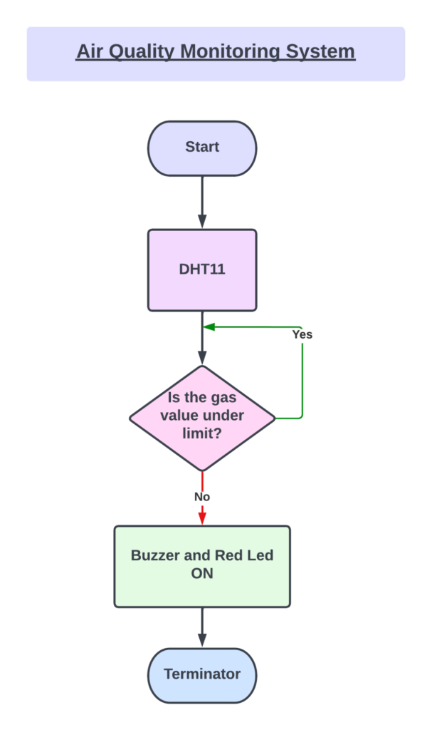
The Air Quality Monitoring System operates by utilizing sensors to detect environmental parameters like gas levels, temperature, and humidity. Specifically, analog readings from the gas sensor, connected to an Arduino's analog pin, provide data on the air quality. The collected data is displayed in real-time on an OLED screen using the

Time Air Pollution Monitoring System ... Circuit Diagram
This project aims to develop a real-time air quality monitoring system using the ESP32 microcontroller and the Blynk IoT platform. The primary goal is to create a portable, cost-effective device that can measure air quality and display the data on a mobile app in real time. By leveraging the capabilities of the ESP32 and Blynk, users can
In this project we are going to make an IOT Based Air Pollution Monitoring System in which we will monitor the Air Quality over a webserver using internet and will trigger a alarm when the air quality goes down beyond a certain level IoT based Air Pollution Monitoring System using Arduino

Based Air Quality Monitoring and AQI Measurement System Circuit Diagram
Testing and calibrating the sensor. The initial step involves calibrating the sensor. To achieve this, connect the sensor to the circuit and allow it to remain powered on for 24 hours to complete