Im trying to build a frequency counter with a Circuit Diagram This document describes the construction of small frequency counter with a cheap PIC microcontroller and a few seven-segment LED digits. The main features of the frequency counter are: In the circuit, use PNP transistors for the CA display instead of NPN for T1 to drive the 5th digit, furthermore connect D1..D4 with reverse polarity, and
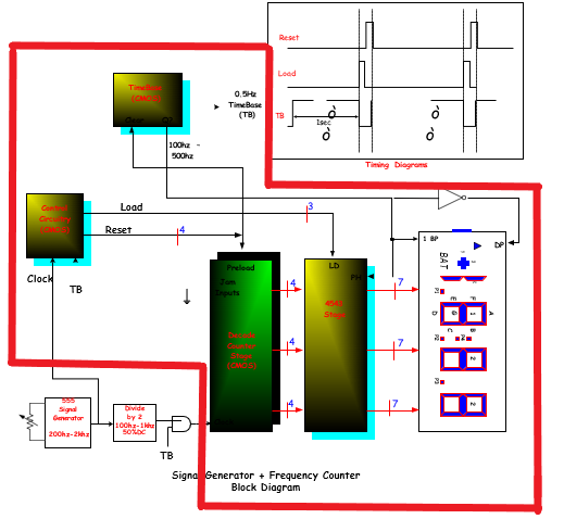
To make calculations trivial using a 1 second gate time (T) gives a direct reading of frequency from the edge counter. Making a frequency counter for frequencies up to 65.536kHz is easy as the counters in a PIC chip can count up to 65535 without overflowing. Up to 65.535kHz all you do is wait for 1 second while the count accumulates, read the Integrated Circuits (ICs) Embedded Computers Enclosures, Hardware and Office Isolators Microcontroller Based Projects; Frequency Counter using Arduino Frequency Counter using Arduino. Published June 13, 2016 40. Dilip Raja

A frequency counter circuit project written in C using TMR1 and an 8 ... Circuit Diagram
Circuit Diagram: Using TIMER of 8051 for Measuring Frequency: 8051 microcontroller is a 8 bit microcontroller which has 128 bytes of on chip RAM, 4K bytes of on chip ROM, two timers, one serial port and four 8bit ports. 8052 microcontroller is an extension of microcontroller. To configure port 3.5 as counter, TMOD register values is set to 0x51.
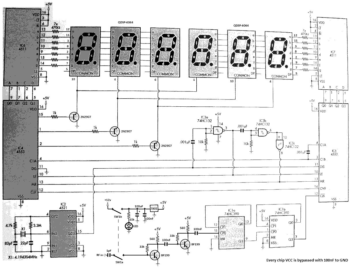
Frequency Counter: Schematics and C code for a PIC frequency counter circuit operating up to about 50MHz. This PIC frequency counter circuit uses a multiplexed seven segment display to provide 8 digits and uses timer 1 to count edges of the input signal and Timer 0 to count time.. It uses the simpler method of direct frequency measurement which means that the input event (for which you want to
8051 Microcontroller based Frequency Counter Circuit Diagram
So what we are going to make is a frequency counter circuit, which can also be called as a frequency meter. To make this frequency meter 1) Simple LED Projects Using AVR Microcontroller. October 11, 2017. Keypad Door Lock using AVR Microcontroller - Atmega16. September 10, 2017. 5 Comments